


How to identify the color code of optical fibers?
Elfcam Official off OLT,
How to identify the color code of optical fibers?
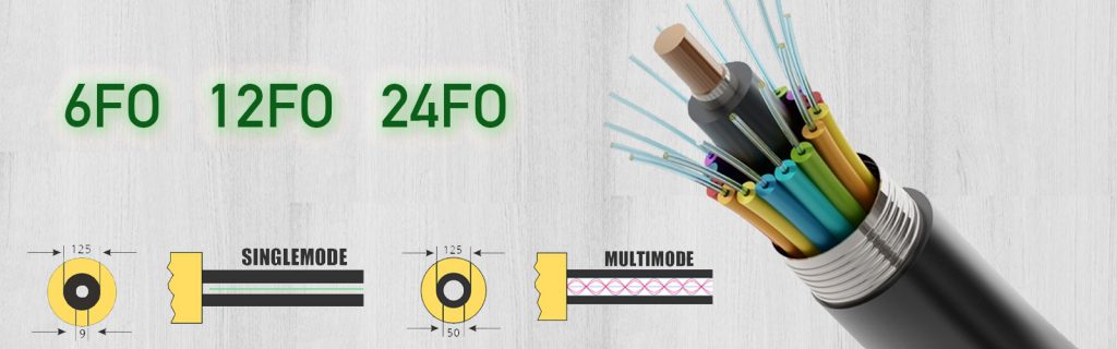
Fiber optic cables are commonly used in laboratories and data centers due to their ability to transmit data at high speed over long distances with very low signal attenuation. Multimode fibers (50/125 and 62.5/125) are often used for short-distance communications, such as within a building or university campus, while single-mode fibers are favored for longer distances, such as inter-building links or extensive telecommunications networks.
However, there is common confusion between multimode and single-mode fibers in multi-fiber cables, where multiple fibers are bundled into a single cable. This confusion can lead to connection errors, affect network performance and increase maintenance costs. The importance of color coding and clear nomenclature is therefore crucial to avoid these misunderstandings and ensure effective management of network infrastructures.
The question arises: How to identify the color code of optical fibers?
The EIA/TIA-598 system is recognized worldwide for its color coding of fiber optic cables. This system greatly facilitates the identification of cables based on the color of their sheath, damper, tube, connector, etc. It is an essential standard for preventing connection errors and maintaining organization in complex environments.
Continuing this logic of clarity, the coding system is also available on the outer sheath of the cables.
Color code for outer sheath
Colored jackets or exterior markings on fiber optic cables are crucial for installations. The EIA/TIA-598 color code specifies jacket colors for different fiber types. In addition, legends printed on the outer jacket of cables containing several fiber types provide additional essential information.
| Fiber Type | Color code | Non-Military Applications | Military Applications | Suggested Printed Nomenclature |
|---|---|---|---|---|
| OM1 62.5/125μm Multimode | Orange | Orange | Slate | 62.5/125 |
| OM2 50/125μm Multimode | Orange | Orange | Orange | 50/125 |
| OM3 50/125 μm (850 nm Laser-Optimized) Multimode | Aqua | Indefinite | Indefinite | 850 LO 50/125 |
| OM4 50/125μm (850 nm Laser-Optimized) Multimode | Aqua/Purple | Indefinite | Indefinite | 850 LO 50/125 |
| 100/140μm Multimode | Orange | Orange | Vert | 100/140 |
| OS1/OS2 Single-mode | Yellow | Yellow | Yellow | SM/NZDS, SM |
| Maintained Polarization Mode | Blue | Indefinite | Indefinite | Indefinite |
Color Code Organization for Internal Fiber Cable
Inside a multi-fiber cable, each fiber is often distinguished by colored casings or tubes. These colors are not arbitrary but follow a specific sequence, and the method of counting (clockwise) for a group of 12 fibers is standardized, thus providing a clear and systematic method for identification.
The details regarding the color sequence and clockwise counting method for a group of 12 fibers are a crucial part of the EIA/TIA-598 coding system. This standardized sequence allows technicians to locate and connect fibers correctly when installing or maintaining multi-fiber cables.
In practice, each fiber within a cable is covered with a distinctly colored jacket. For a set of 12 fibers, the color sequence generally follows the order established by the standard, starting with blue, orange, green, brown, gray, white, red, black, yellow , purple, pink and aqua. When counting, we start with the blue colored fiber and continue clockwise, which corresponds to the order in which the fibers are arranged in the tube or envelope. This method ensures that even if the fibers are extracted from their fixed position, they can be easily identified and replaced correctly.
This colorful arrangement isn't just about convenience; it minimizes the risk of human error and speeds up the identification process, both essential aspects for maintaining the efficiency and reliability of high-speed data communications systems.
Color-coded configurations for multi-fiber cables
In the context of multi-fiber optical cables, the EIA/TIA-598 color coding system offers several configurations to organize and identify multiple fiber strands. These configurations are mainly determined by the number of fibers and their arrangement within the cable.
- First Configuration: 12 Fiber Cables
For cables consisting of 12 fibers or less, each fiber is identified by a unique color according to the standard sequence. This basic sequence is meticulously followed to ensure consistency across the industry.
- Second Configuration: Cables with more than 12 Fibers
When the cable contains more than 12 fibers, the color sequence repeats with variations to distinguish additional groups of fibers. These variations may include bands, rings, or other markings that accompany the base color of the fiber to indicate repetition of the sequence. For example, after using the 12 base colors, a white ring or other secondary color can be added to the sheath of the thirteenth fiber, which would have the same base color as the first fiber in the sequence.
This system makes it possible to manage cables with a large number of fibers without losing the clarity of identification. The repetition of colors with variations is an effective way to maintain order and facilitate technical interventions, essential in environments where speed and precision are essential.
Color code for connectors
Connectors represent a fundamental component of the fiber optic communications system and, as such, they are also integrated into the EIA/TIA-598 color coding system. This color coding of connectors makes it easy to quickly identify the type of fiber they are intended for, reducing the risk of errors when connecting cables.
For multimode fiber connectors, types OM1 and OM2, typically UPC, are often beige or gray in color, which makes them immediately distinguishable from connectors for single-mode fibers. Connectors for OM3 and OM4 laser-optimized fibers, also UPCs, typically feature an aqua color, consistent with the jacket of the cables themselves.
When it comes to single-mode fiber, connectors follow two broad categories based on polish type: UPC and APC. UPC connectors are typically blue, while APC connectors are green. This distinction is crucial because it not only indicates the type of fiber (single-mode versus multi-mode) but also the type of polishing, which impacts the performance of the connection in terms of reflection and signal loss.
| Fiber Types | Polishing Style | Connector Body | Strain Relief Adapter |
|---|---|---|---|
| OM1 62.5/125 | UPC | Beige/Grey | Beige/Grey |
| OM2 50/125 | UPC | Black | Black |
| OM3/OM4 50/125 Optimized laser | UPC | Aqua | Aqua |
| Singlemode | UPC | Blue | Blue |
| Singlemode | Services | Vert | Vert |